Azure Firewall is a cloud native Fire Wall as a Service (FWaaS) offering, that allows you to centrally govern and log all your traffic flows using a DevOps approach. The service supports both application and network level filtering rules and is integrated with the Microsoft Threat Intelligence feed, for filtering the known malicious IP addresses and domains.Azure Firewall is highly available with built-in auto scaling.
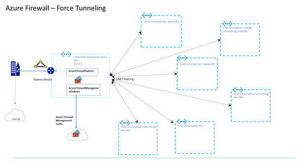
Microsoft Azure firewall offers a feature called “Forced tunneling” which allows one to redirect all internet bound traffic from Azure Firewall to your on-premises firewall via an established VPN connection or an Express Route circuit or to chain it to a nearby network virtual appliance (NVA) for additional inspection. You enable a firewall for forced tunneling when you create a new firewall. It has not been possible to migrate an existing firewall deployment to a forced tunneling mode, till date.
A Real-Life Situation
A customer is building out an environment to perform migration of applications from on-premises to Microsoft Azure. For this environment, customer opted to setup Express Route to establish connectivity between their on-premises data center and Azure.
The customer has a requirement to use BGP (Border Gateway Protocol) to exchange routes between on-premises and Azure.
Additionally, their security team requires all Internet-bound traffic to be piped back to on-premises (force tunneling) through a set of security appliances before being egressed out to the Internet from their data center.
Deployment of Azure Firewall with Force Tunneling
Let’s understand Microsoft articles to deploy the Azure firewall with force tunneling, because if not done in the right way, then the firewall will need to be re-deployed to support force tunneling, there is no direct fix available like troubleshooting the configuration issues.
You can configure Forced Tunneling during Firewall creation by enabling Forced Tunnel mode as shown above. To support forced tunneling, Service Management traffic is separated from customer traffic. An additional dedicated subnet named Azure Firewall Management Subnet (minimum subnet size /26) is required with its own associated public IP address.
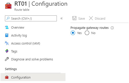
In Forced Tunneling mode, the Azure Firewall service incorporates the Management subnet (Azure Firewall Management Subnet) for its operational purposes. By default, the service associates a system-provided route table to the Management subnet. The only route allowed on this subnet is a default route to the Internet and Propagate gateway routes must be disabled. Avoid associating customer route tables to the Management subnet when you create the firewall.
Within this configuration, the Azure Firewall Subnet can now include routes to any on-premises firewall or NVA to process traffic before it’s passed to the Internet. You can also publish these routes via BGP to Azure Firewall Subnet if Propagate gateway routes is enabled on this subnet.
For example, you can create a default route on the Azure Firewall Subnet with your VPN gateway as the next hop to get to your on-premises device. Or you can enable Propagate gateway routes to get the appropriate routes to the on-premises network.
If you enable forced tunneling, Internet-bound traffic is SNATed to one of the firewall private IP addresses in Azure Firewall Subnet, hiding the source from your on-premises firewall.
If your organization uses a public IP address range for private networks, Azure Firewall SNATs the traffic to one of the firewall private IP addresses in Azure Firewall Subnet. However, you can configure Azure Firewall to not SNAT your public IP address range.
Summary of required parameters:
Azure Firewall Subnet – Forwards internet traffic towards on-premises using this network
Hub Vnet Subnet – The firewall is in this virtual network.
Public IP – Firewall’s Azure Public IP for public interface
VNet-Spoke – The spoke virtual network represents the workload located on Azure
Now, let’s learn to deploy the Azure firewall in Azure portal, there are many options to deploy like using Infrastructure as Code tools (Terraform), PowerShell, ARM templates but here we will consider Azure portal as an option:
2.1. Create the firewall hub virtual network
First, create the resource group to contain the resources:
Sign in to the Azure portal at https://portal.azure.com.
On the Azure portal home page, select Resource groups > Add.
For Subscription, select your subscription.
For Resource group name, type FW-Hybrid-Test.
For Region, select (US) East US. All resources that you create later must be in the same location.
Select Review + Create.
Select Create.
Now, create the VNet:
From the Azure portal home page, select Create a resource.
Under Networking, select Virtual network.
Select Create.
For Resource group, select FW-Hybrid-Test.
For Name, type VNet-hub.
Select Next: IP Addresses.
For IPv4 Address space, delete the default address and type 10.5.0.0/16.
Under Subnet name, select Add subnet.
For Subnet name type Azure Firewall Subnet. The firewall will be in this subnet, and the subnet name must be Azure Firewall Subnet.
For Subnet address range, type 10.5.0.0/26.
Select Add.
Select Review + create.
Select Create.
2.2. Create the spoke virtual network
From the Azure portal home page, select Create a resource.
In Networking, select Virtual network.
For Resource group, select FW-Hybrid-Test.
For Name, type VNet-Spoke.
For Region, select (US) East US.
Select Next: IP Addresses.
For IPv4 address space, delete the default address and type 10.6.0.0/16.
Under Subnet name, select Add subnet.
For Subnet name type SN-Workload.
For Subnet address range, type 10.6.0.0/24.
Select Add.
Select Review + create.
Select Create.
2.3. Create the on-premises virtual network
From the Azure portal home page, select Create a resource.
In Networking, select Virtual network.
For Resource group, select FW-Hybrid-Test.
For Name, type VNet-OnPrem.
For Region, select (US) East US.
Select Next : IP Addresses
For IPv4 address space, delete the default address and type 192.168.0.0/16.
Under Subnet name, select Add subnet.
For Subnet name type SN-Corp.
For Subnet address range, type 192.168.1.0/24.
Select Add.
Select Review + create.
Select Create.
Now create a second subnet for the gateway.
On the VNet-Onprem page, select Subnets.
Select +Subnet.
For Name, type Gateway Subnet.
For Subnet address range type 192.168.2.0/24.
Select OK.
2.4. Configure and deploy the firewall
Now, deploy the firewall into the firewall hub virtual network.
From the Azure portal home page, select Create a resource
In the left column, select Networking, and search for and then select Firewall
On the Create a Firewall page, use the following table to configure the firewall:
TABLE 1
Setting
Value
Subscription
<your subscription>
Resource group
FW-Hybrid-Test
Name
AzFW01
Region
East US
Firewall management
Use Firewall rules (classic) to manage this firewall
Choose a virtual network
Use existing: VNet-hub
Public IP address
Add new: fw-pip
Select Review + create
Review the summary, and then select Create to create the firewall
This takes a few minutes to deploy
After deployment completes, go to the FW-Hybrid-Test resource group, and select the AzFW01 firewall
Note the private IP address. You’ll use it later when you create the default route
2.5. Configure network rules
Add a network rule to allow web traffic.
On the AzFW01 page, Select Rules
Select the Network rule collection tab
Select Add network rule collection
For Name, type RCNet01
For Priority, type 100
For Rule collection action, select Allow
Under Rules, for Name, type Allow Web
For Source type, select IP address
For Source, type 192.168.1.0/24.
For Protocol, select TCP
For Destination Ports, type 80
For Destination type, select IP address
For Destination, type 10.6.0.0/16.
Now add a rule to allow RDP traffic.
On the second rule row, type the following information:
Name, type Allow RDP.
For Source type, select IP address.
For Source, type 192.168.1.0/24.
For Protocol, select TCP.
For Destination Ports, type 3389.
For Destination type, select IP address.
For Destination, type 10.6.0.0/16
Select Add.
2.6. Create and connect the VPN gateways
The hub and on-premises virtual networks are connected via VPN gateways.
2.7. Create a VPN gateway for the hub virtual network
Create the VPN gateway for the hub virtual network. Network-to-network configurations requires a Route Based Vpn Type. Creating a VPN gateway can take up to 45 minutes or more, depending on the selected VPN gateway SKU.
From the Azure portal home page, select Create a resource.
In the search text box, type virtual network gateway.
Select Virtual network gateway, and select Create.
For Name, type GW-hub.
For Region, select the same region that you used previously.
For Gateway type, select VPN.
For VPN type, select Route-based.
For SKU, select Basic.
For Virtual network, select VNet-hub.
For Public IP address, select Create new, and type VNet-hub-GW-pip for the name.
Accept the remaining defaults and then select Review + create.
Review the configuration, then select Create.
2.8. Create a VPN gateway for the on-premises virtual network
Create the VPN gateway for the on-premises virtual network. Network-to-network configurations require a Route Based Vpn Type. Creating a VPN gateway can often take 45 minutes or more, depending on the selected VPN gateway SKU.
From the Azure portal home page, select Create a resource.
In the search text box, type virtual network gateway and press Enter.
Select Virtual network gateway, and select Create.
For Name, type GW-Onprem.
For Region, select the same region that you used previously.
For Gateway type, select VPN.
For VPN type, select Route-based.
For SKU, select Basic.
For Virtual network, select VNet-Onprem.
For Public IP address, select Create new, and type VNet-Onprem-GW-pip for the name.
Accept the remaining defaults and then select Review + create.
Review the configuration, then select Create.
2.9. Create the VPN connections
Now you can create the VPN connections between the hub and on-premises gateways.
In this step, create the connection from the hub virtual network to the on-premises virtual network. You’ll see a shared key referenced in the examples. You can use your own values for the shared key. The important thing is that the shared key must match for both connections. Creating a connection can take a short while to complete.
Open the FW-Hybrid-Test resource group and select the GW-hub gateway.
Select Connections in the left column.
Select Add.
The the connection name, type Hub-to-Onprem.
Select VNet-to-VNet for Connection type.
For the Second virtual network gateway, select GW-Onprem.
For Shared key (PSK), type AzureA1b2C3.
Select OK.
Create the on-premises to hub virtual network connection. This step is similar to the previous one, except you create the connection from VNet-Onprem to VNet-hub. Make sure the shared keys match. The connection will be established after a few minutes.
Open the FW-Hybrid-Test resource group and select the GW-Onprem gateway.
Select Connections in the left column.
Select Add.
For the connection name, type Onprem-to-Hub.
Select VNet-to-VNet for Connection type.
For the Second virtual network gateway, select GW-hub.
For Shared key (PSK), type AzureA1b2C3.
Select OK.
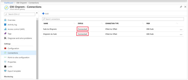
2.10. Verify the connection
After about five minutes or so, the status of both connections should be connected.
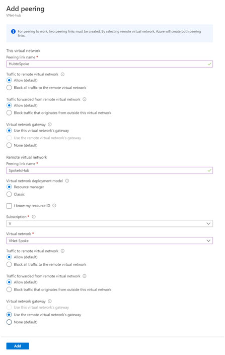
2.11. Peer the hub and spoke virtual networks
Now peer the hub and spoke virtual networks.
Open the FW-Hybrid-Test resource group and select the VNet-hub virtual network.
In the left column, select Peerings.
Select Add.
Under This virtual network:
Setting name
Value
Peering link name
Hub to Spoke
Traffic to remote virtual network
Allow (default)
Traffic forwarded from remote virtual network
Allow (default)
Virtual network gateway
Use this virtual network’s gateway
Under Remote virtual network:
Setting name
Value
Peering link name
Spoke to Hub
Virtual network deployment model
Resource manager
Subscription
<your subscription>
Virtual network
VNet-Spoke
Traffic to remote virtual network
Allow (default)
Traffic forwarded from remote virtual network
Allow (default)
Virtual network gateway
Use the remote virtual network’s gateway
Select Add.
2.12. Create the routes
Next, create a couple routes:
A route from the hub gateway subnet to the spoke subnet through the firewall IP address
A default route from the spoke subnet through the firewall IP address
From the Azure portal home page, select Create a resource.
In the search text box, type route table and press Enter.
Select Route table.
Select Create.
Select the FW-Hybrid-Test for the resource group.
For Region, select the same location that you used previously.
For the name, type UDR-Hub-Spoke.
Select Review + Create.
Select Create.
After the route table is created, select it to open the route table page.
Select Routes in the left column.
Select Add.
For the route name, type ToSpoke.
For the address prefix, type 10.6.0.0/16.
For next hop type, select Virtual appliance.
For next hop address, type the firewall’s private IP address that you noted earlier.
Select OK.
Now associate the route to the subnet.
On the UDR-Hub-Spoke – Routes page, select Subnets.
Select Associate.
Under Virtual network, select VNet-hub.
Under Subnet, select GatewaySubnet.
Select OK.
Now create the default route from the spoke subnet.
From the Azure portal home page, select Create a resource.
In the search text box, type route table and press Enter.
Select Route table.
Select Create.
Select the FW-Hybrid-Test for the resource group.
For Region, select the same location that you used previously.
For the name, type UDR-DG.
For Propagate gateway route, select No.
Select Review + Create.
Select Create.
After the route table is created, select it to open the route table page.
Select Routes in the left column.
Select Add
For the route name, type ToHub.
For the address prefix, type 0.0.0.0/0.
For next hop type, select Virtual appliance.
For next hop address, type the firewall’s private IP address that you noted earlier.
Select OK.
Now associate the route to the subnet.
On the UDR-DG – Routes page, select Subnets.
Select Associate
Under Virtual network, select VNet-spoke
Under Subnet, select SN-Workload
Select OK
Later you can create test virtual machines in the Spoke Vnet and test access towards Azure Firewall for below use cases to verify the force tunneling is working.
First, note the private IP address for VM-spoke-01 virtual machine.
From the Azure portal, connect to the VM-Onprem virtual machine.
Open a web browser on VM-Onprem, and browse to http://<VM-spoke-01 private IP>.
From the VM-On prem virtual machine, open a remote desktop to VM-spoke-01 at the private IP address.
Your connection should succeed and you should be able to sign in that’s all. You are done!